PRESSURE SEAL VALVE
PRODUCTION MATERIALS
Cast Steel Valves Production Range

Production Materials
- Carbon Steel : ASTM A216-WCB or Equivalent
- Alloy Steel : ASTM A217-WC6,WC9,C5,C12,C12A,ASTM A182-F91 or Equivalent
- Stainless Steel : ASTM A351-CF8,CF8M,CF3,CF3M, CN7M or Equivalent
- Duplex Stainless Steel : ASTM A995-1A,2A,4A,5A or Equivalent
- Special Alloy Steel : Inconel 625, Incoloy 825, Hastelloy C, Monel ASME SA designation material
(e.g ASME SA217-WC6)
DESIGN
Pressure seal valve are intended for high pressure and high temperature appilications in all types of fluid, except where severe coking may occur.
A selection of design and material would give an excellent service in nuclear steam generating stations, industrial/chemical plants and thermal power plants.
The pressure seal valve provide the most efficient use for folw passage and sealing, and result in significant weight saving and ease and simple installation and maintenance. Manufacturing and quality assurance procedures include extra controls of dimensional and non-destructive examinations and tests on critical areas such as gasket sealing, weld ends, or stellite sealing surfaces.
CONSTRUCTION
- BODY AND BONNET
- BODY : Flow areas are designed for minimum turbulence and pressure drop.
- BONNET : Ample stuffing box and stellite back seat are to guide accurately stem and back seat.
When designing a PK valve, casting of body and bonnet shall be considered thoroughly as a quality requirement.
- BONNET TYPE
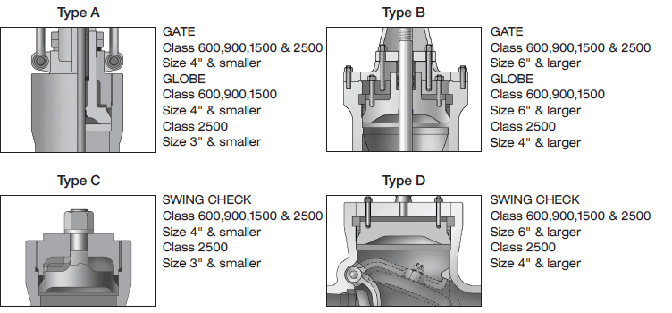
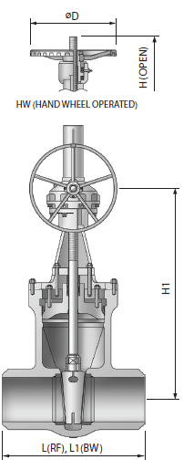
GATE VALVE
FLEXIBLE GATE
A flexible wedge is a one piece and fully guided cast with a central hub allowing the seating faces to move reciprocally and thus compensating for the distortion on body seats due to thermal expansion or pipe loads.
Seat ring and wedge seating face are set to 9°angle from the vertical to minimize the sliding contacts between wedge and seat ring while opening or closing them.
Wedging helps lead to a tight seal in a low differential pressure service.
A flexible wedge resists wedge sticking or binding in a service. The wedge may be closed in a hot condition and opened in cold. The seating surface are stellited to provide high cycle capability in a very high differential pressure service.
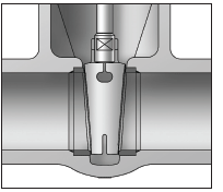
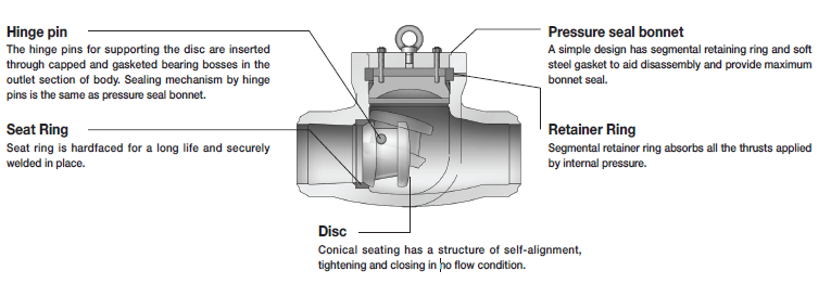
STANDARD PRESSURE SEAL DESIGN
A segment thrust ring absorbs all the thrusts applied by internal pressure. A protective ring made by hardened stainless steel prevents the deformation on the top surface of soft metal gasket. The gasket can be removed smoothly without any damage on the sealing surface of body.
PACKING ADJUSTMENT
All gate and globe valve have a two-piece packing gland to minimize the scoring on valve stem which may occur if tightened unevenly. Gland bolts remain fastened to the bonnet. They swing out of the way to simplify the packing replacement and are oriented to adjust the packing from one side of valve.
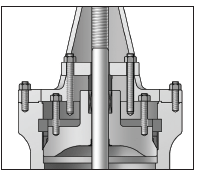
DEEP STUFFING BOXES
Deep stuffing boxes are standard type for gate and globe valve.They allow for extra packing to ensure more reliable stem seal and sufficient packing depth containing an optional lantern ring in the middle of box. where lantern ring is included, a tapped and plugged hole is made. If specified, a ball grease injector can be fitted with.
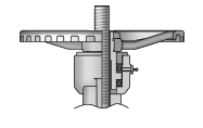
BEARING INSERT TYPE YOKE SLEEVE
Large and high pressure valve may require a tremendous amount of torque to open or close the valve. Ball bearing in the yoke sleeve will reduce the operating torque of valve by up to 50 percent.

SERVICE RECOMMENDATION
1.The gate valve is normally used for on-off service.
It is not recommended for throttling.
2.The gate valve is normally installed to pipe horizontally and the valve stem stands vertically. It can also be mounted to the vertical direction with the stem facing to the opposite or other directions except the vertical, provided that a special construction is prepared depending on the valve size , service conditions, or materials. In case of valve purchase for a special purpose other than the normal installation, the orientation of valve should be specified.
3.After the gate valve is closed completely with a sufficient force enough to shut off, the stem should be backed slightly about 1/8 to 1/4 turn to relieve the load on stem. This will cause the stem to expand a little without valve bending or damage, not affecting the valve shutoff.
END CONNECTION
- R.F FLANGED ENDS TO ASME B16.5
- B.W. ENDS TO ASME B16.25
- R.T.J FLANGED ENDS TO ASME B16.5
- SIZE 26" AND LARGER, FLANGED ENDS
ACCORDING TO ASME B16.47 SER.A OR SER.B
GLOBE VALVE
SERVICE RECOMMENDATION
1.The globe valve is normally installed with flow direction and pressure under the disc. In case the flow in valve directs to the opposite direction, always check at factory before installing the valve. Under a certain service condition, especially when a valve is equipped with cylinders or electric motor actuators, there is a cost advantage in designing and installing the valve flow over the disc. If the actuator is sized to such condition, care must be taken to install the valve correctly.
2. The globe valve is suitable for most throttling applications; however, it must not be used for a prolonged throttling at 10% open or less, which may cause excessive vibration, noise or damage to disc and seat. Use of small valve with a lower flow capacity may permit the valve to be opened to a greater percentage, and thus avoid damage. For continuous severe throttling, a control valve is required.
END CONNECTION
- R.F FLANGED ENDS TO ASME B16.5
- B.W. ENDS TO ASME B16.25
- R.T.J FLANGED ENDS TO ASME B16.5
- SIZE 26" AND LARGER, FLANGED ENDS
ACCORDING TO ASME B16.47 SER.A OR SER.B
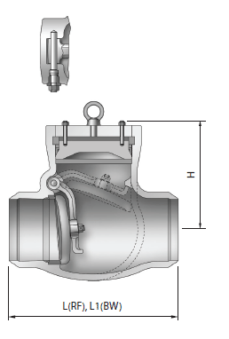
SWING CHECK VALVE
SERVICE RECOMMENDATION
1.The swing check valve shall be opreated in a manner to avoid the following troubles;
1)Formation of excessive high surge pressure as a result of valve closing, and
2)Rapid fluctuating movement of valve closing member. The excessively high surge pressure by valve closing is prevented by closing the valve fast enough not to develop a significant reverse flow on a sudden shutoff which is a source of the surge pressure. Thus, the closing speed of valve should match closely with the speed of forward flow retard.
The rapid fluctuating movement of valve closing member must be avoided to prevent the moving valve parts from excessive wear which may result in early failure of valve.
Such movements can be precluded by sizing the valve to a flow rate which forces the closure member not to move.
2.The swing check valve can also be mounted to the vertical position, provied the disc should not reach the valve position. However, the closing moment of disc by weight is very low in fully-opened position, so the valve tends to close late.
In order to overcome such slow response to flow retardation, the disc may be supplied with a lever-mounted weight or with spring loaded.
TILTING DISC CHECK VALVE
TILTING DISC CHECK ADVANTAGES
- Quick closing system
- Stability at low and pulsating flow
- Moderate pressure drop
- Tight sealing of metal seats
Seat contacts don’t occur until the disc is seated and closed.
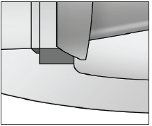
DOUBLE OFFSET
A high performance tiling disc check valve has double offset pivot(hinge pin) design.
The pivot offsets are made when constructing the valve with hinge pins which are located behind the centerline of sealing surface and slightly to one side of pipe centerline.
The offset purpose is to reduce rubbing and thus wear between seat and seal while valve is travelling.
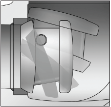
OFFSET 1
The hinge pin is located in the centerline of disc seal surface.
OFFSET 2
The hinge pin is offset to the conical axis.
SERVICE RECOMMENDATION
1.The center of gravity of disc is very close to the axis or rotation, so that the disc can be opened or closed very quickly without damage to the body, disc or seat. Since the valve is closed quickly upon flow reversal significant fluid velocities are not developed in the reverse direction, therefore minimizing the effects of water hammer.
2.The tilting disc check valve has greater stability at low flow rates and in pulsating service when compared to a swing check valve.
3.The pressure drop across a tilting disc check will usually be much less than for an equivalent life check. Although a tilting disc check valve will restrict flow slightly more than a swing check, the straight-through flow path provides a minimal pressure drop.
4.Tilting disc check valve have moderate sealing capability and can provide tight shutoff if the differential pressure across the disc is relatively large.
DESIGN DATA FEATURES
1. Face to face & end to end dimensions : ASME B 16.10
2. Flanged dimensions : ASME B 16.5
3. Butt welded end dimensions :ASME B 16.25
4. Valve size (if applicable) and ratings :ASME B 16.34
5. Wall thickness dimensions of valve comply with API 600